Electrical Wiring Diagrams
To understand how to read ladder wiring diagrams, let's start with a simple electrical schematic consisting of a power supply, switch, and light.
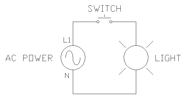
To begin understanding how to read and understand electrical circuit diagrams, take our basic circuit and draw it out as it would physically be wired. We show our AC power source on the left with L1 and N coming out of it, our switch to the top, and our light to the left. Power comes out of L2 to the switch, which when open, breaks the circuit preventing current flow and when closed, ties the left and the right terminals of the switch together, allowing current flow. The switch is connected to the light, then there is a neutral or return wire back to the power supply.
This makes it really clear when representing simple circuits with basic electrical symbols but imagine you had 10 switches and ten lights. Very quickly, this simple diagram would turn into a great big mess. If you notice our "Getting Started Wiring Guide" omitted half the trainer. If we had represented a wiring example of the entire trainer in this manner, you would not be able to follow it.
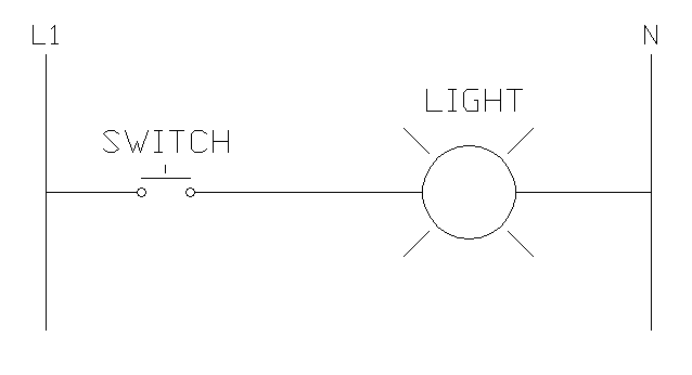
So to simplify this, your power wires, in this case L1 and N, run vertically down the page. Then circuits off of it such as our switch/light run horizontally on "rungs". As you draw out these circuits the diagrams begin to take the shape of a ladder which is where ladder diagrams get their name.
Usually, if it is three phase then L1, L2, and L3 run down the left side of the page and if there is a neutral (N) then it runs down the right side of the page. In single phase diagrams L1 will run down the left side of the page and N or L2 will run down the right side of the page.
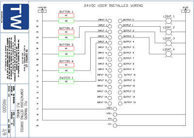
The power source, if external to the drawings, is usually not shown. This will become clearer when you begin working with our control panel sample wiring diagrams in the exercises below.
The next key advantage of ladder wiring diagrams over drawing circuits is the way they are physically laid out so that they are indexable, meaning device names can give you the page and rung number that the device can be found on in the ladder wiring diagrams. Also devices that may span multiple locations in a drawing such as a relay coil and its contacts can easily be cross referenced.
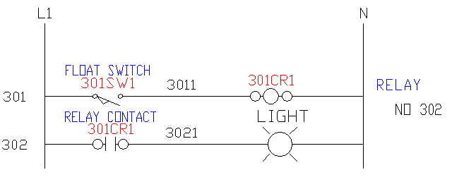
For example, study the diagram to the right. Our power source L1 and N are running vertically as you have learned and now you have added rung numbers to the left of the ladder for reference. These usually increment by one as you go down the page and may incorporate the page number into the rung number. So, in this case, the three probably represents page 3, then you are looking at Rung 01 and 02. Everyone does it a little bit different but once you understand the basics it only takes a few minutes of examining most sets or drawings to follow them.
Now let's look closer at how this works.
Looking at Rung 301, you have a switch labeled 301SW1. That means it is on Rung 301, it is a switch (SW), and usually there will be a number that increments by one from left to right. So if we had a second switch it would be labeled 301SW2. The switch would be labeled 301SW1 in the field. That way when someone looks at the switch, they know exactly where to find it in the wiring diagram
Next you see a label "3011". This is the wire number of the wire that connects the switch to the relay and it should be labeled as such on each end of the wire and in any junctions that connects it. This way if someone sees this wire number, they know to go find Rung 301 then find the first connection point. Also note that the wire to the left of the switch is not labeled because it is connected to L1 which is labeled at the top. With very few exceptions, connections that are physically connected, such as L1 is to the float switch, should keep the same wire label, in this case L1, throughout the drawings.
Now you are at the relay coil. This is an important concept to grasp. It is not the entire relay that you would physically hold in your hand. It is only the coil that, when energized, pulls in the relay contacts. It is labeled 301CR1 which again is the rung number, CR for control relay or contactor/relay, then 1 which is an incremental number to identify it from a second relay that may be on the same rung. Being able to find its contacts is a key advantage of ladder wiring diagrams. There is usually a cross reference to the right of the relay coil along with the description that will tell you where the relay contacts are used, in this case a normally open (NO) contact is used on Rung 302. If this diagram were physically laid out with the coil and contacts in the same place, the more complex the system, the more the wires would have to cross causing much confusion. For an example of this, have a look at a typical automotive wiring diagram.
Before you move on to Rung 302, let's make sure you understand that the conditions of Rung 301 do not affect having power at the beginning of Rung 302. Since the vertical lines on each side tie 301 and 302 together, they both receive power via L1 and N the same way. Note that there can be breaks in these vertical lines that can make this not true but we'll address this in a later lesson.
Looking at Rung 302, you can follow many of the same concepts you learned on 301. You have a relay contact but instead of being labeled 302CR1 such as switch 301SW1 was in Rung 301, it is labeled 301CR1. This is because the coil of this relay is in Rung 301. So if this contact was on Rung 999, it would still be labeled 301CR1. This lets you know where the coil that controls it is located.
Then you see the label "3021" which is the same principle that we discussed on Rung 301.
And last you have our light which is connected to the neutral completing our circuit.
While you have only reviewed a few rungs, these concepts are the basics that all ladder wiring diagrams use. Study the sample drawings to the right.