Analog, Math, and Scaling
In this lesson you will continue with the program you created in the RsLogix 500 - Analog Circuits - Wiring and Programming - 0-10VDC 4-20mA lesson.
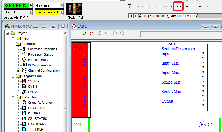
1. Add an SCP instruction. It can be found on the Advanced Math tab of the Tabbed Instruction Bar which is the far right tab. This is a good time to practice your online editing which you learned in the Rslogix 500 - Online Edits lesson.
2. In the RsLogix 500 - Analog Circuits - Wiring and Programming - 0-10VDC 4-20mA lesson you learned that the Input Min. and Input Max. will be 0 and 32,767, the full voltage scale is 0-10.5 VDC, and the full current scale is 0-21mA.
3. From the information in step 2, enter the following into the SCP instruction.
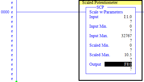
Input - I:1.0. You will learn more about the details of addressing later but for now:
I - Input
1 - Slot 1
0 - Channel 0 or analog input 0
Input Min. - 0
Input Max. - 32767
Scaled Min. - 0
Scaled Max. - 10.5
Output - F8:0 - This is a floating point data type which will allow you to see a decimal representation of the analog signal.
4. Accept the changes, test, and assemble the edits.
5. Take a volt meter and set it to DC voltage. Measure the voltage between terminal 2 of the potentiometer and the 0VDC terminal blocks and note how the reading on the volt meter matches the value of F8:0. You may be wondering why the value is maxed out around the 11 o'clock position. In later lessons you will use the full range of the potentiometer.
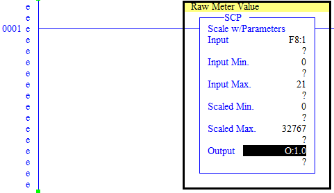
6. Create a second SCP below the one you created. This one will be used to scale the output going to the meter. To start you will configure the SCP so that you can enter 0-21 "mA" instead of 0-32,767 by entering the following parameters:
Input - F8:1
Input Min. - 0
Input Max. - 21
Scaled Min. - 0
Scaled Max. - 32767
Output - O:1.0
7. Accept the changes, test, and assemble the edits. Did you get an "Unable to create data table" error when you tried? If so, go offline, make the change, download the program, then go online. You will learn more about it in the RsLogix 500 - Data Table Types and Sizing lesson.
8. Open up the F8 data table and enter 4 in F8:1 and you should see the meter jump up to 1. 8 takes it to 2, 12 takes it to 3, 16 takes it to 4, and 5 takes it to 20.
9. It is still difficult to remember that 4 in the data table is 1 on the meter, 8 in the data table is 2 on the meter, 12 in the data table is 3 on the meter, 16 in the data table is 4 on the meter, and 20 in the data table is 5 on the meter. Using online edits change the Input Max. of the SCP in Rung 1 to 5. Now 1 in the data table is 1 on the meter, 2 in the data table is 2 on the meter, 3 in the data table is 3 on the meter, 4 in the data table is 4 on the meter, and 5 in the data table is 5 on the meter. You can also enter decimals. Enter 1.5 into the data table and the meter will be in the middle of 1 and 2.
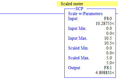
10. Using online edits, add one more rung to your program and put an SCP in it with the following parameters.
Input F8:0
Input Min. - 0
Input Max. - 10.5
Scaled Min. - 0
Scaled Max. 5
Output F8:1
11. Now turn the potentiometer between the far left position and the 11 o'clock position and notice how the meter follows it.
12. If you are wondering how this works, it uses the same scan steps you learned in the RsLogix 500 - Seal In Rung and PLC Scan Explanation. Break these three rungs down step by step and make sure you understand how they work.
These analog skills along with why you learned in the previous lessons are enough to do some complex programming.