Analog, Math, and Scaling
Eventually, maybe even before this lesson in your series, everyone has to deal with PLC faults.
If a PLC is faulted, it's FAULT LED on the front of the PLC will either be Solid or Flashing.
Solid Fault Light - This means that the PLC has a hardware issue. There is no recovering from this and the PLC will have to be replaced.
Flashing Fault Light - This means the PLC has an application fault. This is much more common than the solid fault light and recoverable. But before you recover from it, make sure you understand what caused it or at least gather all information available to help you prevent it from happening again. Below are the steps for identifying, understanding, and clearing faults.
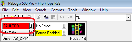
1. Go online with the PLC. Where your PLC would normally say RUN or REM RUN, it will show faulted.
2. Click the right down arrow beside FAULTED and click "Goto Error". DO NOT click the "Clear Fault" yet.
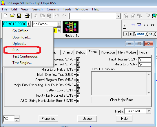
3. The "Goto Error" brings up the S2 - STATUS data files "Errors" tab. There is a lot of great information on this tab to help you diagnose your problem. Below is a description of each bit but perhaps the most important one is the Error Description which will give you details about the PLC fault.
Fault Override at Powerup S:1/8
When set, this bit causes the controller to clear the Major Error Halted bit S:1/13 and Minor error bits S:5/0 to S:5/7 on power up if the processor had previously been in the REM Run mode and had faulted. The controller then attempts to enter the REM Run mode. Set this bit offline only.
Startup Protection Fault S:1/9
When this bit is set and power is cycled while the controller is in the REM Run mode, the controller executes the user fault routine prior to the execution of the first scan of your program.
Major Error Halt S:1/13
This bit is set by the controller any time a major error is encountered. If a major fault state exists, you must correct the condition causing the fault, and then clear the fault.
Math Overflow Trap S:5/0
When this bit is set by the controller, it indicates that a mathematical overflow has occurred in the ladder program.
Control Register Error S:5/2
The LFU, LFL, FFU, FFL, BSL, BSR, SQO, SQC and SQL instructions are capable of generating this error. If this bit is set, the error bit of a control word used by the instruction has been set.
Major Error Executing User Fault Return S:5/3
This bit is set while processing a fault routine (due to a major error) another major error occurs.
Battery Low S:5/11
This bit is set whenever the Battery Low LED in on. This bit is cleared when the Battery Low LED is off. It is updated only in the REM Run or REM Test modes.
Input Filter Selection Modified S:5/13
This bit is set whenever the input filter selection in the controller is made compatible with the hardware.
ASCII String Manipulation Error S:5/15
This bit is set (1) when an attempt is made to process a string using an ASCII instruction that exceeds 82 characters in length.
Fault Routine S:29
You enter a program file number (3-255) to be used in all recoverable and non-recoverable major errors. Program the ladder logic of your fault routine in the file you specify. Write a 0 value to disable the routine.
Major Error S:6
A hexadecimal code is entered in this word by the controller when a major error is declared. This word is not cleared by the controller. Click here for a complete list of the errors in the MicroLogix controllers with suggestions for possible remedies.
Error Description
A read-only description of the error is provided here. Click the Clear Major Error button to clear any indication of a major fault. Always make sure that the condition that resulted in the error has been corrected first. Click here for a complete list of the errors in the MicroLogix controllers with suggestions for possible remedies.
3. Specifics on the Expansion I/O module error - If you get this error with our trainer, chances are you created a new program and forgot to go to the I/O Configuration in the left pane and add the 1762-IF2OF2 in slot 1. Go to the RsLogix 500 - What can you learn from a blank program lesson for details on adding this module to your program.
4. After you understand the error, to clear it click the down arrow to the right of "FAULTED" and select "Clear Fault".
5. Click "Yes" to verify you want to clear the error.
6. The fault will be cleared, but the PLC will not go back into RUN mode. It will be in PROGRAM mode.
7. To put it back into RUN mode click the down arrow beside REMOTE PROG and click "Run". If your PLC immediately faults then you have not fixed the problem causing the fault.
In later lessons we will go through the specifics of some other faults.
Start your hands-on training: Micro850 PLC Trainer