Analog, Math, and Scaling
In this lesson you will wire the potentiometer and analog meter of your trainer to your PLC.
1. Add the following wires to your trainer. The analog terminals can be found in the expansion slot to the right of the base PLC. You are wiring your potentiometer as a voltage input. Turn the potentiometer dial fully counterclockwise.
2. In the top of your PLC analog module you will find two DIP switches. Switch 1 will need to be in the OFF position for voltage mode. When wiring for current, you would put it in the ON position. This is engaging a load resistor when you will learn about in a later lesson.
3. Open up RsLogix 500 and create a new file by clicking the white icon in the top left corner of RsLogix 500.
4. Select "Bul 1763 Micrologix 1100 Series B" as the processor type and click the OK button.
5. In the left pane, double click on "IO Configuration".
6. Drag the "1762-IF2OF2" from the "Current Cards Available" on the right to the #1 slot on the left.
7. Double click the 1762-IF2OF2 you just added to slot 1.
8. Click on the Analog Configuration tab and in the Outputs section select "4 to 20mA" for the Output Range of Channel 0 then click the OK button. With this configuration you will be using 0-10VDC on input 0 and 4-20mA on output 0. If you need a refresher on these two types of analog signals see the RsLogix 500 - Understanding Analog Circuits 0-10VDC 4-20mA lesson.
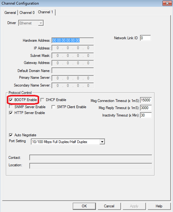
9. In the left pane, double click on "Channel Configuration".
10. Click the "Channel 1" tab.
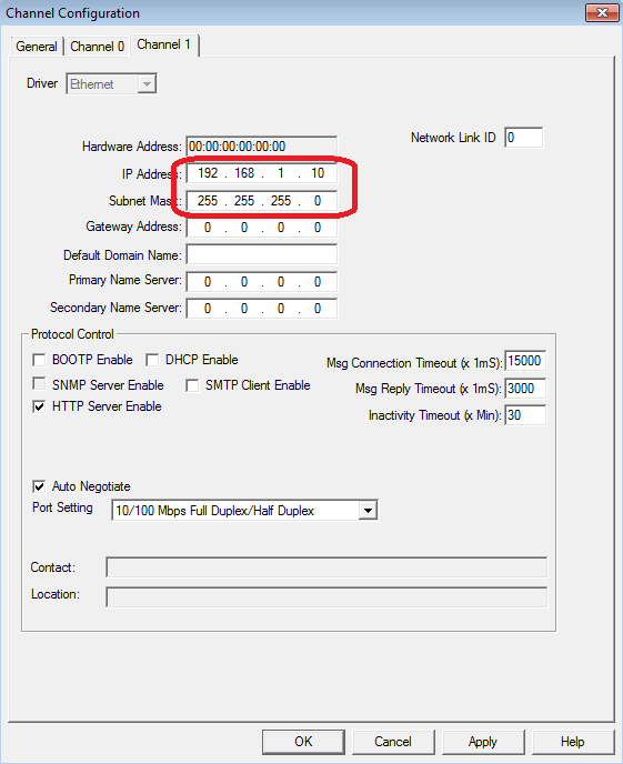
11. The IP settings will be grayed out until you uncheck the "BOOTP Enable" option.
12. Now you can enter a manual IP address. Enter the default IP address of your trainer which is 192.168.1.10 with a subnet of 255.255.255.0.
13. Go to Comms >System Comms...
14. Navigate to the PLC via the configuration you setup in RsLinx at the beginning of this lesson. THIS IS IMPORTANT! As you learned in the lesson on "Uploading a Program from a PLC", you Upload FROM a PLC and you download TO a PLC which is the opposite of the internet. Click the "Download" button to send your program to the PLC.
15. If you have not saved your program yet, you will be prompted to save it before downloading.
16. One last chance to realize you are downloading to the PLC which will overwrite any existing code in the PLC. Click the "Yes" button.
17. To begin your download, the processor must be switched to Program mode. By default your trainer is in Remote mode which allows it to be switched via RsLogix. Make sure your PLC is in remote mode then click the "Yes" button.
18. If your channel configuration, which is how you connect to the PLC, is different than what was in the PLC previously, you will be warned. Make sure that the Channel Configuration is correct then click the "Apply" button.
19. If you want to go online select the "Yes" button.
20. Where you see "REMOTE PROG", click the down arrow to the right of it and select "Run".
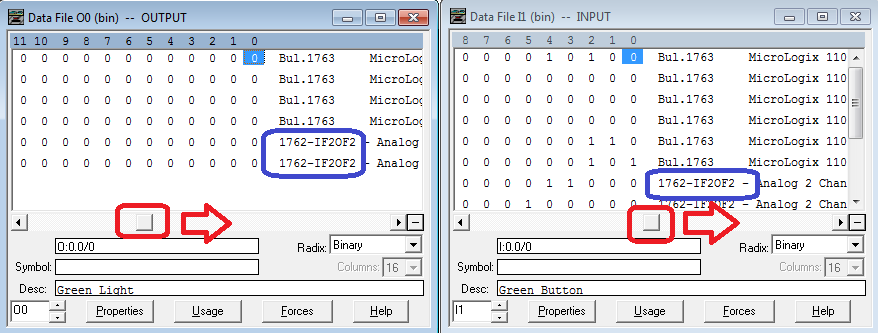
21. You will be prompted to make sure you want to switch the processor to RUN mode. Click the "Yes" button.
22. Open up the O0 and I1 data tables circled below.
23. Trying to navigate to the correct address can seem difficult at times. The default view when you open the input and output data tables obscures a very important feature that can help you. Click the left/right scroll bar of both data tables and drag them to the right as shown below. The far right column identifies which module the data table row is associated with.
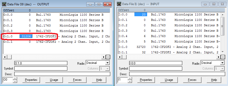
24. Select the Radix on each data table view and select "Decimal".
25. You can now see a decimal view of the analog inputs and analog outputs. You will probably notice some small values in the analog inputs even when wires are not connected to the PLC. These small values are normal.
26. Turn the potentiometer slowly clockwise and you will see "I:1.0" increase until the potentiometer is approximately straight up and down or at the 6 o'clock position. At that point it should be near 32,767. Is your potentiometer working backwards as in all the way to the right is near 0 instead of all the way to the left? Simply swap the wires connected to terminals 1 and 3.
27. Now you are probably wondering, what does that 32,000 value mean? The answer to that is in the 1762-IF2OF2 installation manual in the general specifications. The "Full Scale Analog Range" which for voltage is 0-10.5VDC. That means that 0-10.5VDC equals 0-32767 units in the PLC. Since they both start at 0 then we can do a simple equation of Voltage*32,767/10.5=units. Alternately Units*10.5/32,767=Voltage. You'll learn how to easily scale these in the next lesson, RsLogix 500 - Analog Scaling.
28. Now enter some values into the 0:1.0 data box. A few notable ones are 6241 will be 1, 12,482 will be 2, 18,724 will be 3, 25,965 will be 4, and 31,206 will be 5 on the analog meter.
29. Those numbers seem random but if you refer back to the General Specifications, the "Full Scale Analog Range" for current is 0-21mA which equates to 0-32,767. So dividing 32,767 by 21, each mA is approximately 1,560 units.